Click here to download manual
Click here to download product literature
Electronic Surface Profile Gage for Blasted Steel and Textured Coatings
Digital spring micrometers measure and record surface profile parameters using Testex Press-O-Film replica tape producing a more
accurate peak-to-valley height measurement.
-
Ready to measure no calibration adjustment required for most applications
-
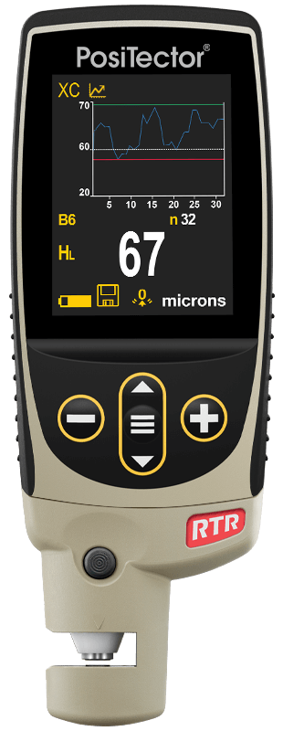
NEW Larger 2.8 inch impact resistant color touchscreen with redesigned keypad for quick menu navigation
-
NEW Weatherproof, dustproof, and water-resistant - IP65-rated enclosure
-
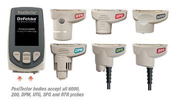
PosiTector interchangeable platform - attach any PosiTector probe to a single gage body
-
USB, WiFi, and Bluetooth connectivity to PosiSoft PC, Mac, and Smartphone software
-
Certificate of Calibration showing traceability to PTB included (Long Form)
Conforms to ASTM D4417, ISO 8503-5, NACE RP287, SSPC-PA 17, SSPC-SP5, SP6, SP10, SP11-87T, and others
-
Statistics mode continually displays/updates average, standard deviation, min/max, and number of readings while measuring
-
NEW Screen Capture save 100 screen images for record keeping and review
-
NEW Instant-on feature quickly powers up the gage if recently powered down
-
NEW Up to 30 percent longer battery life
-
USB port for fast, simple connection to a PC and to supply continuous power. USB cable included
-
PosiSoft USB Drive stored readings and graphs can be accessed using universal PC/Mac web browsers or file explorers. No software required.
-
Every stored measurement is date and time stamped
-
Software Solutions for viewing, analyzing and reporting data
-
Software Updates via web keep your gage current
Includes ALL features as shown on Above plus...
Includes ALL features as shown on Above plus...
-
NEW Storage of 250,000 readings from multiple probes in up to 1,000 batches
-
Live graphing of measurement data
-
NEW Touchscreen keyboard for quickly renaming batches, adding notes, and more
-
WiFi technology wirelessly synchronizes with PosiSoft.net and downloads software updates
-
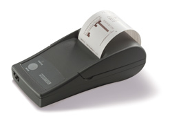
Bluetooth 4.0 Technology for data transfer to a mobile device running
the PosiTector App or optional portable printer. BLE API available for integration into third-party software.
-
Integrate with third-party software, drones, ROVs, PLCs, and robotic devices using several industry-standard communication
protocols
|
Specifications
|
Peak Height (HL)
Measurement Range
|
20 to 115 μm
(0.8 to 4.5 mils)
|
|
Peak Height (HL) Accuracy
|
± 5 μm (± 0.2 mils)
|
|
Peak Height (HL) Resolution
|
1 μm (0.1 mils)
|
|
Anvil Diameter
|
Ã6.35 mm (Ã0.25 inch)
|
|
Anvil Pressure
|
1.1 Newtons (110 gram-force)
|
|
Size
|
127 x 66 x 25.4 mm
(5 x 2.6 x 1 inch)
|
|
Weight
|
137 g (4.9 oz.) without batteries
|
Size and weight are for the PosiTector gage body only and do not include the probe
Measuring Surface Profile Parameters
using the PosiTector RTR and Replica Tape
Testex Press-O-Film replica tape consists of a layer of compressible foam affixed to an incompressible polyester film of highly uniform thickness. When pressed
against a roughened steel surface, the foam forms an impression, or reverse replica, of the surface.

Placing the compressed tape (replica) between the anvils of the PosiTector RTR provides surface profile parameters.
PosiTector RTR-H models measure peak-to-valley surface profile height (HL).
PosiTector RTR-P models also measure peak density (Pd). Advanced RTR-P models generate 2D/3D images
and SDF Surface Data Files.
PosiTector RTR-H
Measures peak height (HL) by placing the compressed replica tape between the anvils. The 2 mil (50.8 micron incompressible film is automatically subtracted
and the peak height measurement is displayed.

PosiTector RTR-P
In addition to measuring peak height (HL) , the PosiTector RTR-P provides areal peak density (Pd) - the number of peaks per unit
area.

The RTR-P incorporates a digital camera and light source. Light is passed through the replica tape and imaged by the camera.
Peak counts can be determined by simply counting bright spots on the photograph as taken by the PosiTector RTR's digital image sensor
(camera).
The intensity of light that passes through the replica tape is inversely proportional to the thickness of the compressed foam. The below photograph of a back-lit
piece of replica tape reveals light areas of higher compression (peaks) and dark areas of lower compression (valleys).

|
|
2D image derived from replica tape
|
Digitally counting bright spots or peaks
|

PosiTector RTR-P Advanced models can save high resolution SDF surface data files. These files can be imported into third-party image rendering/analysis
software. See Surface Data File (SDF) and 3D Surface Mapping for an overview.
Q. Are there different models of the PosiTector RTR to choose from?
A. Yes. In addition to Standard or Advanced features, there are now two probes (RTR-H and RTR-P) to
choose from for measuring replica tape . . .
PosiTector RTR-H:
⢠measures peak to valley surface profile height in accordance with ASTM D4417 Method B
PosiTector RTR-P:
⢠measures peak to valley surface profile height in accordance with ASTM D4417 Method B
⢠measures areal peak density
⢠generates high resolution 3D images of the measured surface *
* Available only when the PosiTector RTR-P probe is attached to an Advanced body. This combination provides on-screen 2D
and 3D thumbnail images of the surface for reports and an SDF (surface data file) for high resolution 3D analysis by third-party software.

Q. Can I purchase only the PosiTector RTR probe for my existing
PosiTector?
A. Yes. PosiTector bodies manufactured after April 2011 with serial numbers greater than 700,000 support
both probes (RTR-H and RTR-P). Simply update your existing PosiTector by following step by step instructions at www.defelsko.com/update/
Q. Why is surface profile measurement important?
A. Steel surfaces are frequently cleaned by abrasive impact prior to the application of protective coatings. The resultant surface profile
must be accurately assessed to ensure compliance with job or contract specifications. In the protective coatings industry, replica tape is widely used for quantifying surface profile.
Peak height and peak density are important factors in the performance of applied protective coatings. Low values may reduce coating bond
strength (adhesion). High values may cause peaks to receive insufficient coverage and possibly rust prematurely and for the surface to be insufficiently wetted.
Q. What is replica tape?
A. Replica tape is a long known method for characterizing a surface. It is simple, relatively inexpensive and shows good correlation with
results from other methods. It is particularly useful for measurements on curved surfaces that are difficult to measure directly with stylus instruments, interferometric laser scanning or optical
focal distance measuring devices. It is therefore not surprising that it has become the most popular field method for measuring surface profile. Its operation is described in a number of
international standards including ASTM D4417 , ISO 8503â5 , NACE RP0287 , and AS 3894.5.
Replica tape consists of a layer of compressible foam affixed to an incompressible polyester film of uniform thickness (2 mils +0.1 mil). When pressed against
a roughened steel surface the foam forms an impression or reverse replica of the surface. Placing the compressed tape (replica) between the anvils of a micrometer and subtracting the contribution
of the incompressible polyester film (2 mils / 50.8 μm) gives a measure of the average maximum peakâtoâvalley surface roughness profile.

Q. Why have you created a new PosiTector RTR-P probe?
A. It is not widely known that surface replicas obtained using Testex Tape contain far more information than just peak height as measured
by a micrometer or by our PosiTector RTR-H. Significant data is available through digital imaging. The PosiTector RTR-P uses thickness and imaging sensors to characterize replica
tape and generate images and statistics of the original surface.
The nature of abrasive blast cleaned steel surfaces is predictive of long term coating performance. The most important of these
parameters, peak height (H), is commonly measured today and is usually the only parameter reported. While its importance is undeniable, one parameter alone does not fully describe the dynamics of
a coating/substrate relationship. Peak density (Pd) is also an important indicator of performance. Together with H, Peak density provides a better prediction of long term coating
performance.
Replica tape has been used to measure the profile of abrasive blasted steel since the late 1960's. Compared to other methods, it has the
advantages of ruggedness, relatively low start-up cost, good repeatability and the option of retaining a physical replica of the surface being evaluated. This method is widely used and
understood.
Q. Why is it important to measure peak density?
A. The figure below is a simplified example of why BOTH peak height AND peak density are important to the understanding of coating
performance. The two surfaces have different geometries yet their height measurements are the same. Peak density measurements give a clearer picture of the surface available for
bonding.

Both surfaces have the same measured peak-to-valley height. A second important measurable parameter, peak density, helps explain why coatings bond differently to each
surface.
Q. If it is so important to count peaks, why has the industry not been doing it?
A.  There is little doubt that peak density measurements are important. The problem has been that they have not been easy to obtain.
Stylus roughness instruments (contact profilometers) have been the only devices available. They measure both peak height (Rt) and the number of peaks encountered along a sampling length (Pc) as per
ASTM D7127. They have not become popular for economic and practical reasons.
They are fragile in nature since they depend on a precisely calibrated stylus that often extends a distance from the body of the device
itself. They can be complex to set up and to operate, and they report a number of roughness parameters that are of limited interest to the coatings industry. Finally, these instruments have a
significant initial cost. All these factors dissuade potential users.
Q. How does the PosiTector RTR-P get peak density information from Replica
Tape?
A. Replica tape has been used to measure the profile of abrasive blasted steel since the late 1960's. Compared to other methods, it has the
advantages of ruggedness, relatively low start-up cost, good repeatability and the option of retaining a physical replica of the surface being evaluated. The method is widely used and widely
understood. But it is not widely known that surface replicas obtained using Testex Tape contain far more information than just peak height as measured by a micrometer.
Significant data is available through digital imaging. The PosiTector RTR-P captures an image of light passing
through the burnished tape which reveals light areas of higher compression (peaks) and dark areas of lower compression (valleys). The gage simply counts the bright spots.
Q. Are PosiTector RTR-P peak density values the same as peak count
values generated by surface roughness instruments?
A. Stylus roughness instruments record the up and down distances of an external stylus traversing across a surface. They count the number
of peaks (Pc) encountered along a straight 12.5 mm (0.5 in) line. The PosiTector RTR-P counts the number of peaks from a replica tape surface area that is approximately 16 mm2
(0.63 in2). Although stylus roughness instruments yield a 2D measurement in peaks/mm (peaks/in) and the PosiTector RTR-P series yields measurements in peaks/mm2
(peaks/in2), the two methods correlate well.
Q. What is a 2D thumbnail image?
A. A black and white two dimensional (2D) image is essentially a photograph of the burnished tape. It reveals a pattern of dark and light
spots similar to what you might see if you put the replica tape in front of a light source. The bright areas are higher compressed tape (peaks) and dark areas are lower compressed tape (valleys).
Peak density is determined by simply counting the bright spots. This exportable image is suitable for inspection reports.

Q. What is a 3D thumbnail image?
A. Additional surface characterization parameters can be extracted once the 2D image has been generated. The
PosiTector RTR-P uses a light intensity versus thickness algorithm to produce three dimensional (3D) images of the replicated surface. A low resolution color image is quickly
generated and displayed on the PosiTector which can also be exported into inspection reports.

Q. What further analysis can be done by third-party software?
A. In addition to producing 2D and 3D images of every replica tape measurement, the PosiTector RTR-P3 (with an Advanced body) can
also generate an SDF (surface data file) that can be imported into free or purchased third-party rendering software. The result is a 3D map of the blasted steel surface at a cost far less than
interferometric or confocal profiling devices.
See Surface Data File (SDF) and 3D Surface Mapping

Q. Can PosiSoft.net store and report all this new PosiTector RTR-P
data?
A. Our free, cloud based PosiSoft.net website will store and report all PosiTector RTR data including peak to valley height
(HL), peak density (Pd), and each measurement's 2D and 3D thumbnail image. SDF files are not available on PosiSoft.net.
Q. Can the PosiTector RTR give the same measurement results as Testex spring
micrometers?
A. The user has a choice of measurement modes with the PosiTector RTR. The default mode is HL. This value is the most
accurate peakâtoâvalley height measurement because it adjusts for tape nonâlinearity without the need to average 2 or more replicas.
The user can change the gageâs measurement setting to report an H measurement value that is comparable to the value obtained by Testex spring micrometers after the
subtraction of the 2 mil / 50.8 μm incompressible polyester substrate.
Q. Why are PosiTector RTR measurements more accurate than those of spring
micrometers?
A. We determined the nonâlinear relationship between actual steel profile peakâtoâvalley heights and their replicated heights on tape.
Using this algorithm the PosiTector RTR is able to overcome the shortcomings imposed by the nonâlinearity of replica tape foam. With a single measurement, the gage produces a more accurate
peakâtoâvalley height measurement HL. The advantages are a reduction in measurement uncertainty, inspector workload, the likelihood of error, and the number of replicas needed by
inspectors to assure accuracy.
In other words, the PosiTector RTRâs displayed HL value is a more accurate surface profile measurement because it adjusts for
tape nonâlinearity without the need to average the results from 2 or more replicas.
Q. What is meant by the word linearization?
A. Linearization is a technique used to insure uniform accuracy of measurement in many types of advanced
sensors. Its use in connection with replica tape is described here.
Q. How does the anvil impact force of the PosiTector RTR compare to that of spring
micrometers?
A. They are the same. Mitutoyo micrometers supplied by Testex have had special modifications made to their springs and anvils. The
PosiTector RTR has the same anvil size (0.25 inch / 6.25mm diameter) and applies the same spring tension (110 gramâforce / 1.1 Newtons) as Testex micrometers and as required by major test
standards.
An issue with mechanical spring micrometers is that they can underâread if users drop the measuring anvils onto the replica tape too fast. Other errors can occur if
users press upward on measuring arms to âstabilizeâ readings. Both actions force conventional micrometers to read lower by crushing the tapeâs delicate microfoam.
The PosiTector RTRâs unique opposing spring design prevents these undesired user interferences from happening. Pressing the two probe buttons releases a holding
spring. That allows a second spring, the anvil spring, to apply a constant pressure measuring force on the replica. This measuring force is not coupled to the buttons so the user cannot alter the
applied pressure and inadvertently influence results.
Q. Does the PosiTector RTR measure ALL grades of replica tape?
A. The PosiTector RTR measures the two primary grades of replica tape: Coarse and XâCoarse. The other grades of replica tape,
Coarse Minus and XâCoarse Plus, are check grades that are used only to confirm or improve the accuracy of conventional analog spring micrometer measurements at the lower end of the Coarse
tapeâs range (Coarse Minus) and at the upper end of the XâCoarse tapeâs range (XâCoarse Plus). Since the PosiTector RTR automatically corrects for the nonâlinearity of Coarse and XâCoarse
tape, these other check grades are not required.
To get best quality high resolution SDF images of the original surface, DeFelsko recommends the use of Optical Grade Testex tape.
Q. What is Optical Grade Testex tape?
A. For improved optical resolution and to reduce optical artifacts in SDF images, the Testex Company manufactures an optical-grade version
of their Coarse and X-Coarse grade tapes.
Q. Why is a stainless steel burnishing tool included instead of a plastic swizzle stick?
A. DeFelsko has taken steps to improve on all aspects of the replica tape surface profile measuring process including the initial replica
creation. Plastic sticks are not manufactured to uniform tolerances and their ball ends often contain sharp knit lines from the molding process. The ball on the supplied stainless steel burnishing
tool is machined to the proper diameter for optimal rubbing. It wonât break under pressure and ensures a consistent test is accomplished every time.

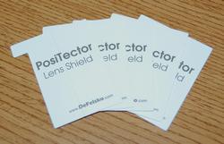
Q. Why is an Anvil Cleaning Card included?
A. The anvils of all measuring devices quickly become dirty with residual tape adhesive and with grit picked
up from the test surface. Frequent cleaning is recommended to ensure accuracy. A cleaning card is included with every PosiTector RTR and additional cards are available in packs of 20. They
can be used with most micrometers.
Ensuring the anvils are clean is especially important when using the PosiTector RTR-P to measure peak density (Pd) and generate
surface images.

Q. Why is Surface Cleaning Putty included?
A. Abrasive blasting leaves grit on test surfaces that gets picked up by the crushable foam in replica tape.
This debris affects the accuracy of replica tape measurements made by any micrometer and should be removed from the test surface with the included putty. This putty was tested amongst many and
works the best in all environments. Other, similar putties will not work well in extreme environments and may contaminate the surface instead of cleaning it. One package of Surface Cleaning Putty
is included with every PosiTector RTR and additional putty is available in packs of 5.
Ensuring the surface is clean is especially important when using the PosiTector RTR-P to measure peak density
(Pd) and generate surface images.


Q. What is the purpose of the included check shim and check tape?
A. The PosiTector RTR Check Shim verifies the accuracy and operation of the peak
height measuring system. The Peak Density Check Tape verifies the operation of the peak density measuring system.
Q. How do you position replica tape into the PosiTector RTR?
A. Testex PressâOâFilm replica tape is now produced with two positioning dots that align with arrows located
on both sides of the PosiTector RTRâs probe. Move the tape to the back of the probe, align the dots, and then press the two probe buttons. Measurement is fast, simple and accurate.




 Standard Models
 Includes
all features shown on the at a glance tab plus...


 There is little doubt that peak density measurements are important. The problem has been that they have not been easy to obtain.
Stylus roughness instruments (contact profilometers) have been the only devices available. They measure both peak height (Rt) and the number of peaks encountered along a sampling length (Pc) as per
ASTM D7127. They have not become popular for economic and practical reasons.


